


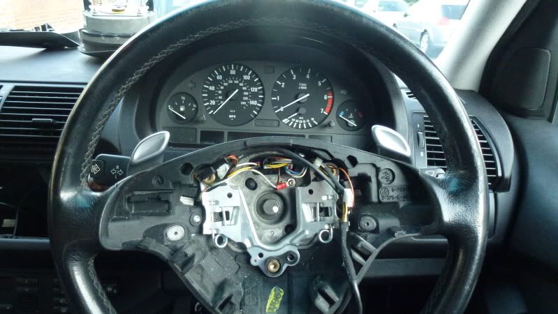
This is the wheel I bought, you can see the paddles dont have the + and - on them ( should have picked up that clue )
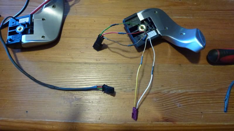
These are the switches removed, I have stripped back the heat shrink to expose the wires to aid in the probing. There is a master switch that goes on the left and a slave swith that goes on the right. What we need is the green wire connecting to ground - 0 volts and the brown and or red switching to 0 volts when the switch is pulled or pushed.
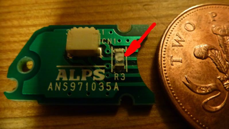
This is the circuit board off one of the switches with the resistor arrowed that needed to be removed.
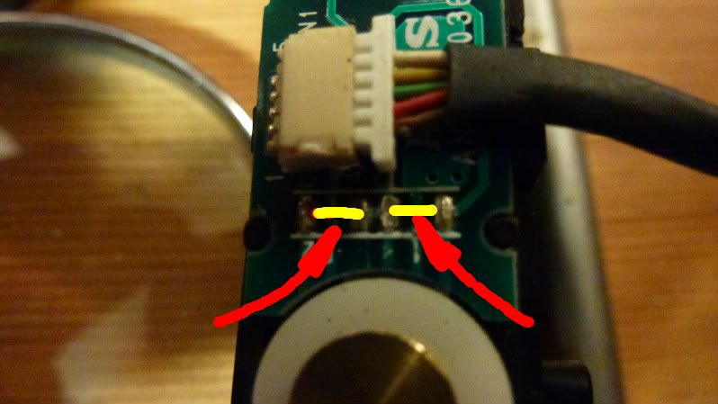
This is the other switch with the ( two ) resistors removed
This is the master
Here is the master switch after some fancy re-wiring
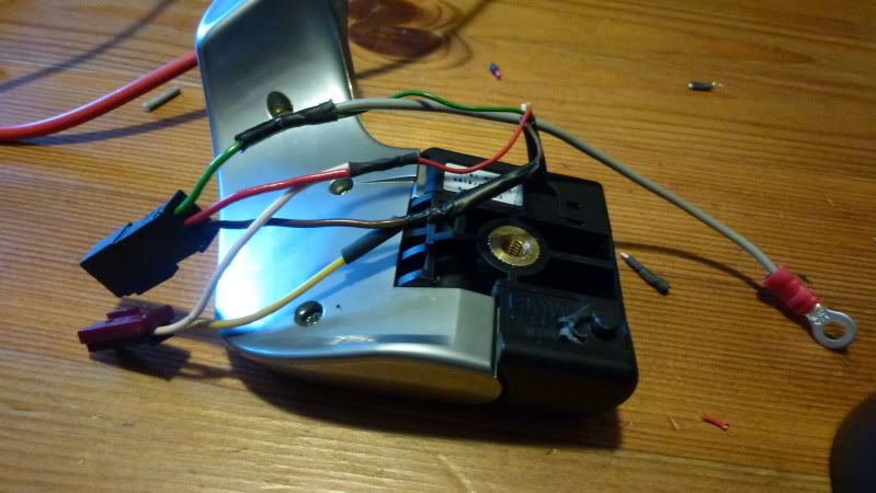
The yellow and white wires that go to into the master switch are now redundant. The plug was nipped off and the wires grafted onto the red and brown wires while a seperate ground wire was connected into the green wire.
I would like to report it is all functioning as it should - it almost is, I have up and down shift on one paddle but only up on the other paddle, I suspect I neeed to bridge a couple of connectors in the master switch. I will report back as and when.If anyone wants any further info feel free to give me a shout.

