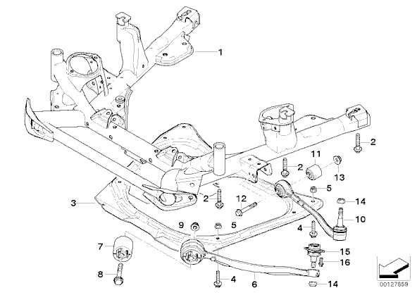
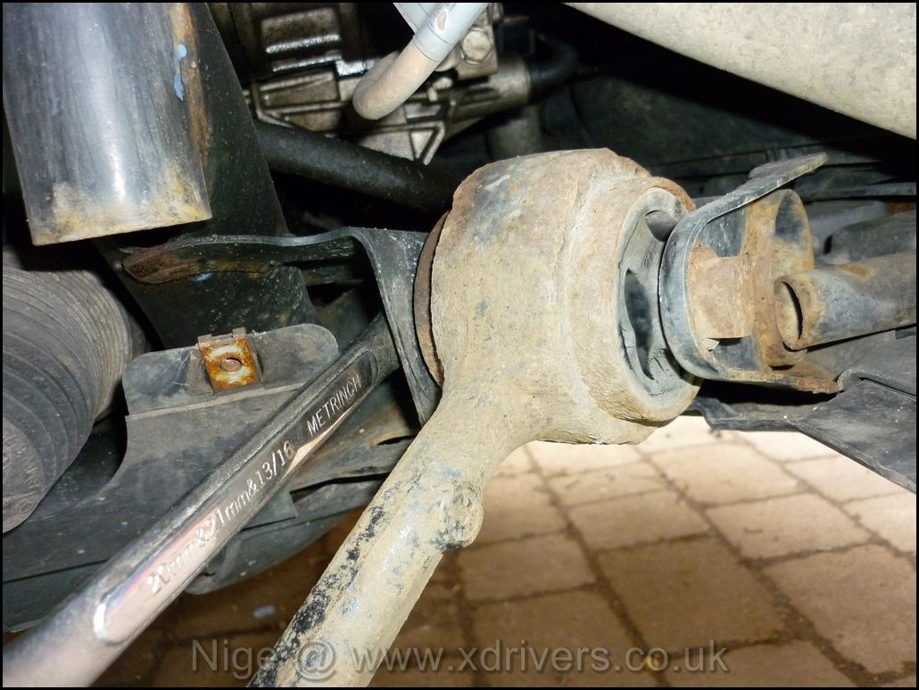
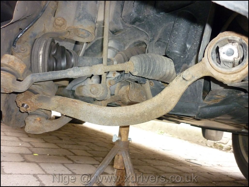
By laying on my back, grabbing the Tension arm in the middle and twisting, it was obvious the bush (#7) was worn as cracks in the bush could be seen when twisting it.
Bush #7 can be bought for about £35 and pressed into place, however I don`t have access to a suitable press and was short of time. 2 new Tension arms were £65 ea from my local motor factors.
Start by removing the front roadwheel and securing the car on axle stands.
Remove the small 8mm bolts holding the inner arch liner in place (many were rusted and needed a pair of mole grips to loosen them)
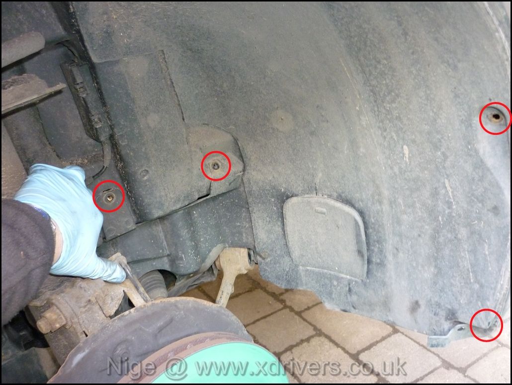
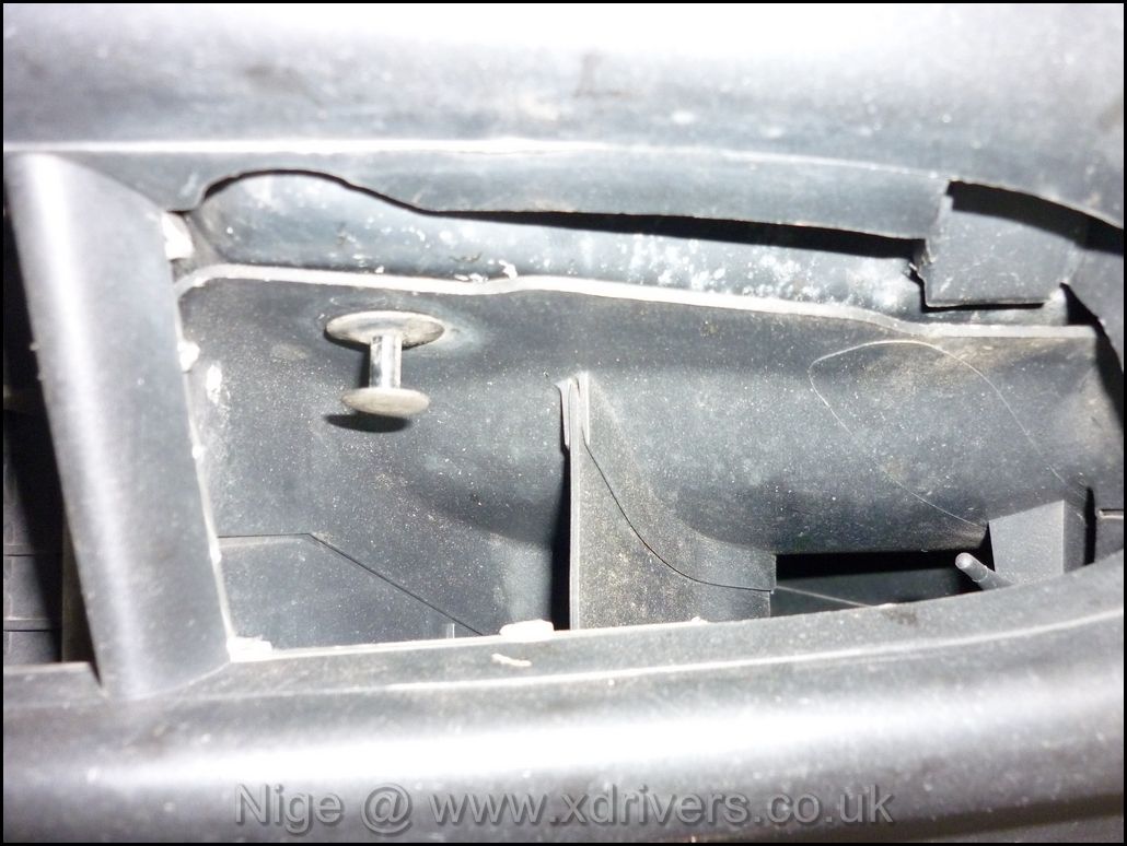
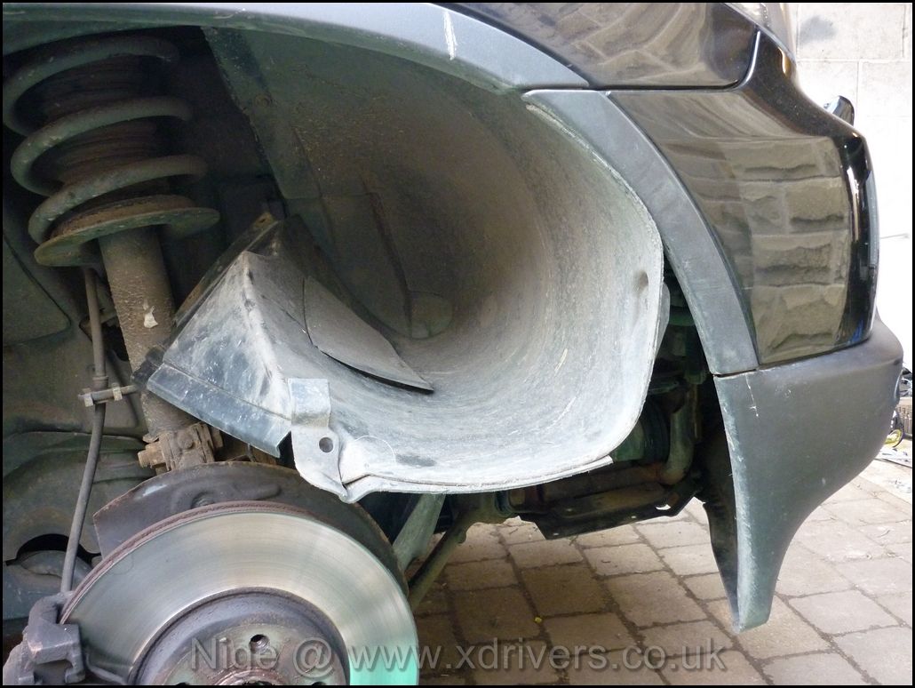
The arch can then be `peeled` back, this was easier than fully removing the entire liner. Once done, the brake duct needs removing by taking out the 4 screws. On the passenger side, the external air sensor is fitted to the duct, so be careful not to pull the wires out. The plastic guard over the steering arm was also remove to make access easier.
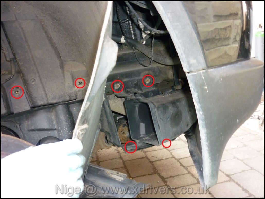
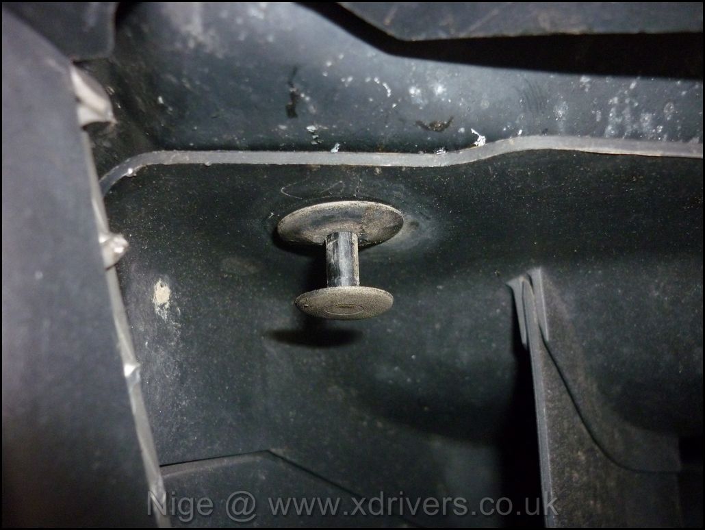
There is also a plastic clip that can be accessed from the front bumper with a screwdriver, the centre needed to be pulled out.
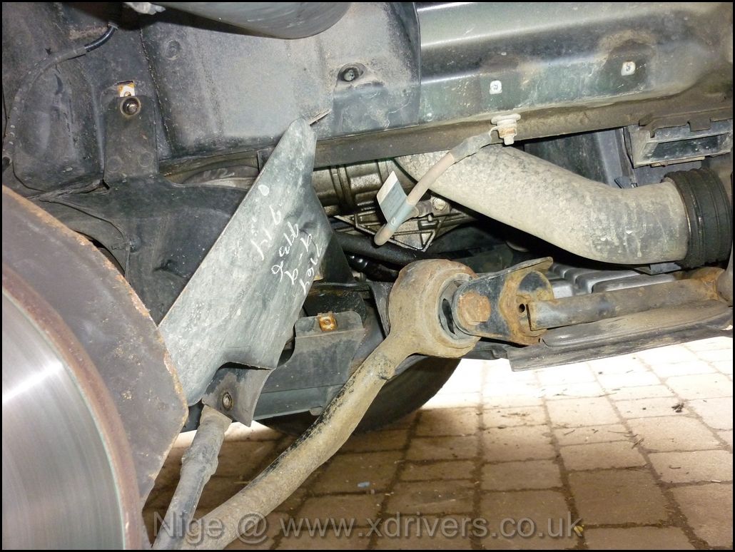
External air temp sensor can just be seen at the bottom right of the photo
Arch peeled back and wedged in place
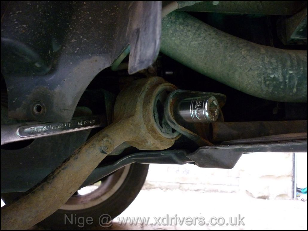
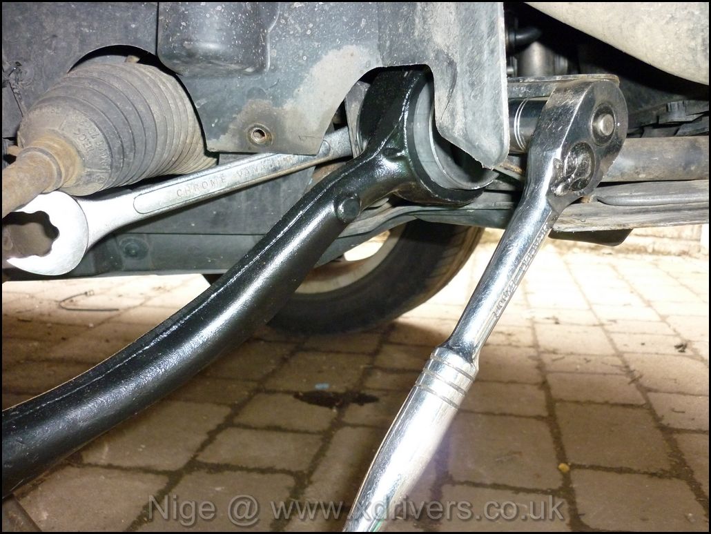
The tension arm securing bolt.
Access for the nut is very tight, so I used a ring spanner to lock the nut.
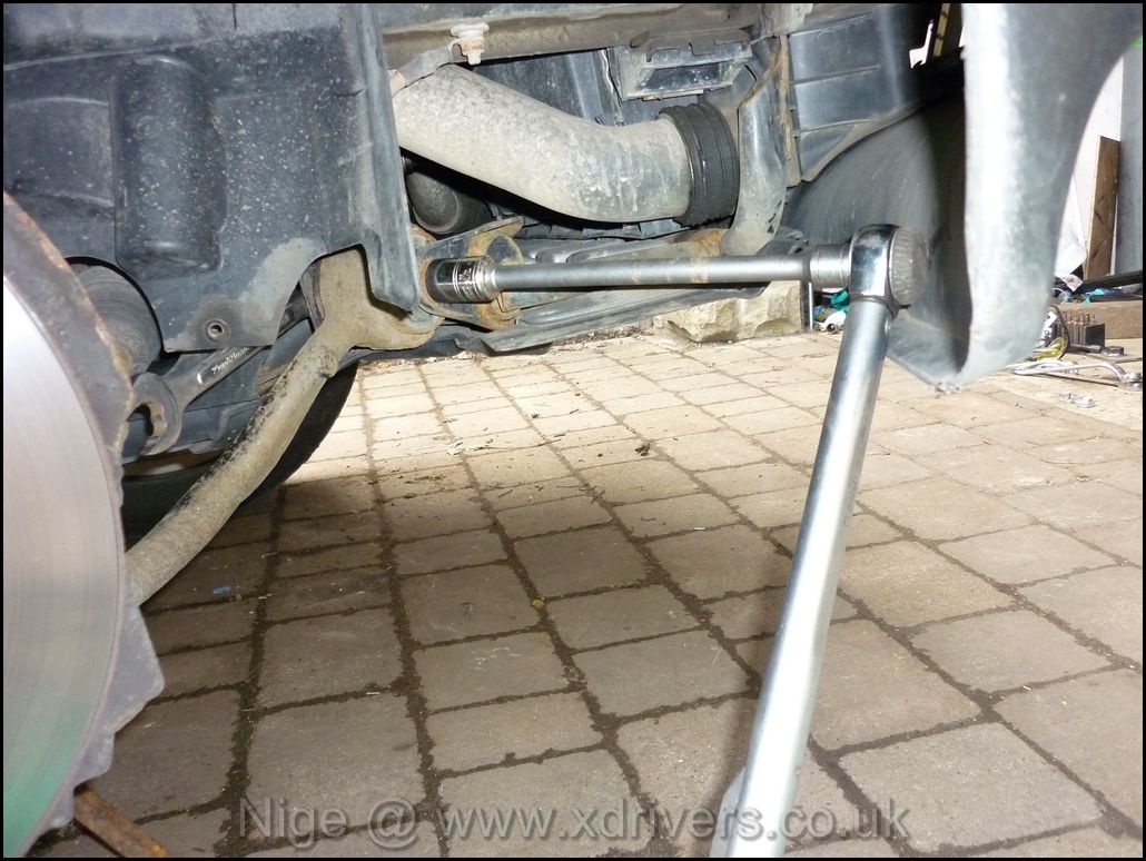
Socket onto the Bolt
long bar is needed to loosen the bolt.
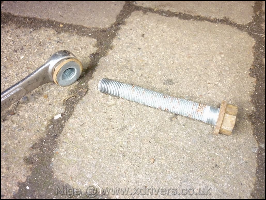
Once removed, place to one side.
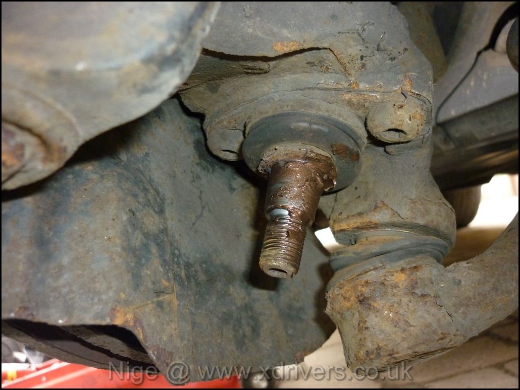
The large nut holding the arm to the balljoint can be removed.
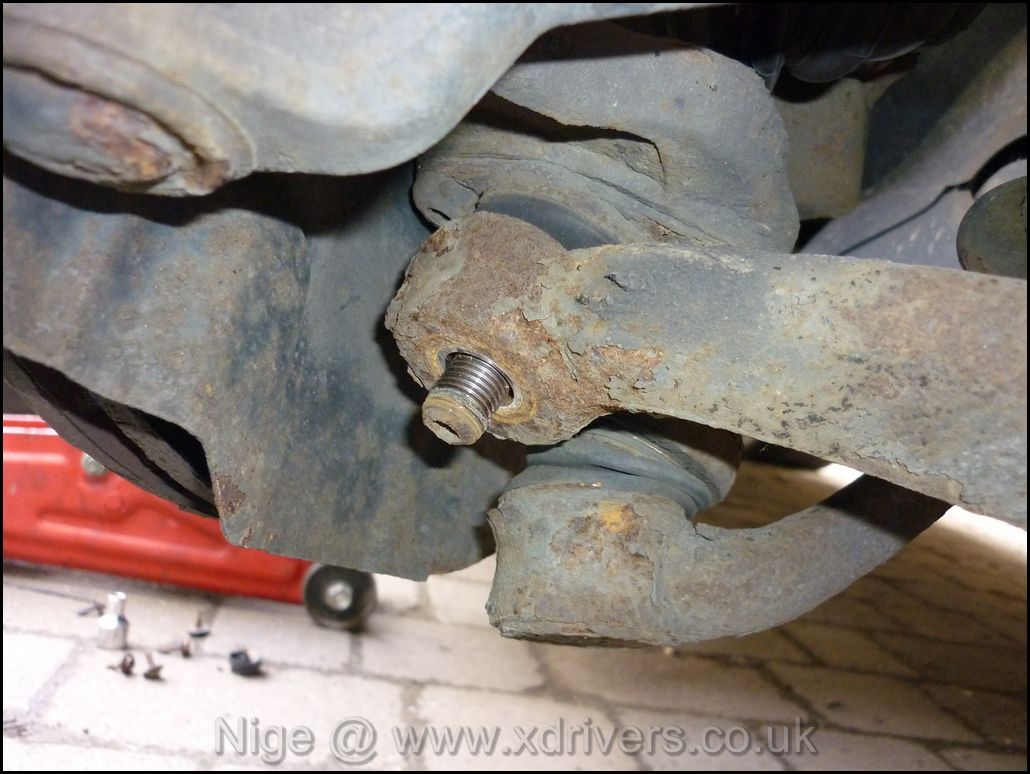
Ready for removal..
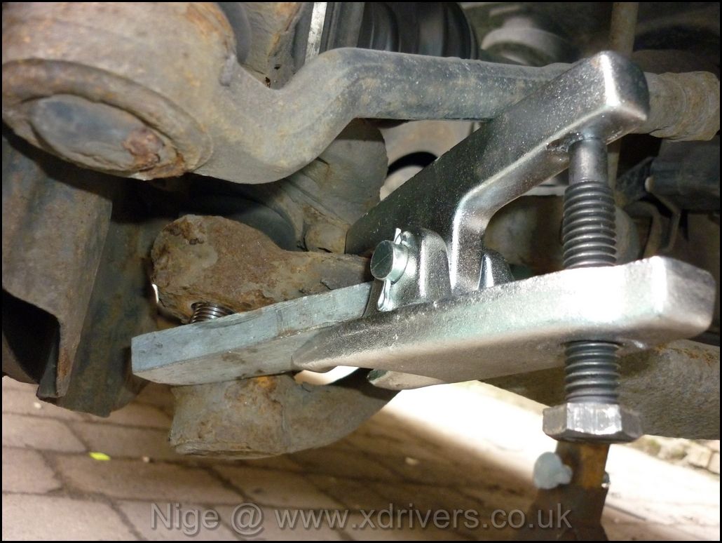
This is where a balljoint splitter is required. I didn`t have one large enough and had to manage with a 19mm one. It made the job much more difficult. on my car, this has been in situ for 90,000 miles and 6 years. It was `secure`...
Some people hit the top of the arm with a large hammer and knock it off the balljoint, but I was reluctant to do this for fear of damaging the balljoint (#15) in the process.
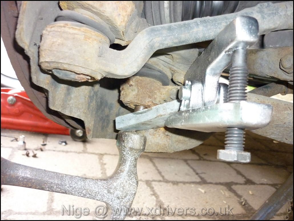
I used a piece or bar to put tension on the balljoint frmo the balljoint splitter.
Hitting the end of the balljoint, whilt it is under tension did the trick for me. Each side probably took 30 minutes to actually remove the arm from the balljoint. They are tight, but DO come off with perseverance.
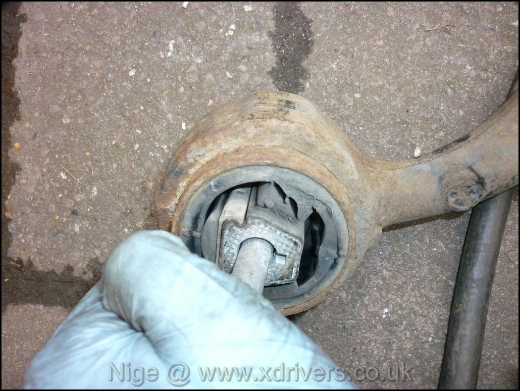
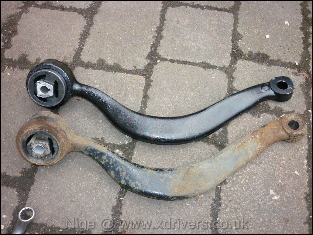
Once removed, it was immediately obvious how much the old bush had worn
New arm next to old one
Copperslip applied to balljoint taper to enable easier removal if needed in future..
.
Refitted the arm into the chassis mount
I then refitted the plastic trip, ensured everything was secure and repeated on the other side. The vibration is gone and the car sailed through the MOT.
Hope this helps.
Nige.